Water droplets

Monitoring Relative Humidity in Controlled Environments

Relative Humidity and Controlled Environments

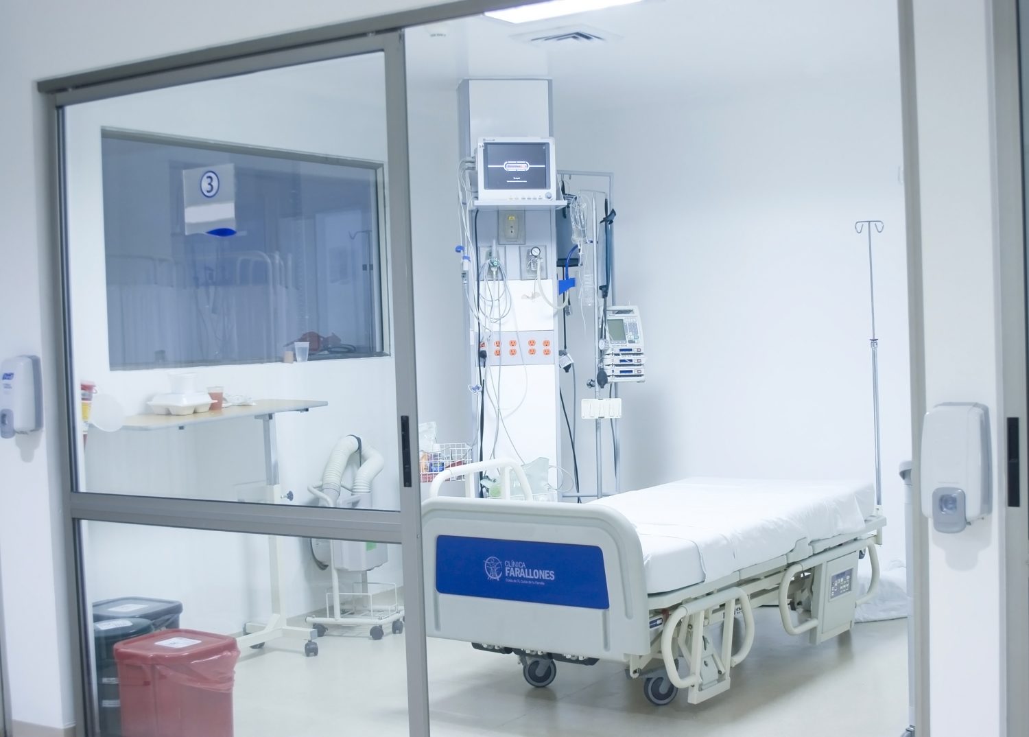
Relative Humidity (RH) is one of many important variables monitored and controlled in cleanrooms, negative and positive pressure rooms and generic controlled environments. Some specific types of controlled environments, such as USP 797 pharmaceutical-based rooms require close monitoring and control of relative humidity; other industries monitor and control humidity as a means of preserving product efficacy and quality.

Basically, relative humidity (RH) is the amount of moisture in the air compared to what the air can “hold” at the current temperature…

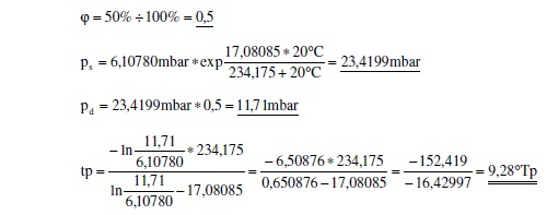
More precisely, relative humidity is the actual vapor density divided by the saturation vapor density multiplied by 100%. So, an example would be:

Readings from measuring instruments: temperature = 20.0 °C
Relative Humidity = 50%

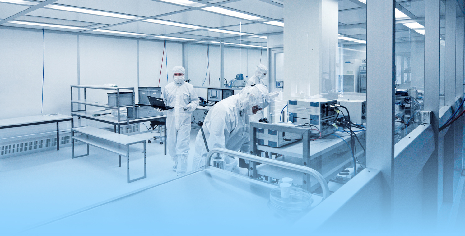
In semiconductor cleanroom operations, relative humidity is held to much stricter standards. Typical values range from 30 to 50 percent with tolerances as narrow as ± 1 percent for some areas, such as photo-lithography. Ranges may be even less for deep ultraviolet processing (DUV).

An often overlooked capital expense within cleanroom operations is maintaining desired relative humidity ranges in makeup air. All too often, expenses associated with maintaining adequate filtration, and keeping low particulate counts are the focus of controlled environment design and operation, while variables such as temperature and relative humidity are considered. This can be a major miscalculation.  If humidity gets out of control product integrity can also get out of control.

Why it matters

So, why go through all of the planning and expense to build and maintain a controlled environment and devote so much time to monitoring relative humidity? Quite simply because relative humidity affects not only room temperature (another important variable) but could degrade overall cleanroom performance and even potentially adversely affect the health and well being of cleanroom personnel and the general public.

Failure to maintain and control relative humidity could result in:

  • Metal corrosion
  • Static charge buildup
  • Moisture condensation
  • Photolithographic degradation
  • Water absorption
  • Bacteria growth
  • Mold growth
  • Pathogen growth
  • Personnel comfort
  • Temperature control
  • Filtration effectiveness
  • Fungi growth
  • Prevent/Cause chemical reactions
  • Affect adhesives and solvents
  • Dirtier overall controlled environment
  • Static electricity

Preventing Adverse Effects

In environments where relative humidity is at or above 60% it can be especially difficult to control or prevent the growth and contamination of:

  • Bacteria
  • Mold
  • Fungii
  • Viruses

Conversely, relative humidity lower than 30% can cause personnel discomfort such as:

  • Dry and cracked skin
  • Dryness in the eyes and mucous membranes
  • Respiratory discomfort
  • Electrostatic buildup and discharge

A compromise for both personnel comfort and product safety and efficacy is in the 40% to 55% range. In cases where more or less humidity is required that may result in personnel discomfort, additional safety procedures are taken to prevent electrostatic buildup and discharge. An example would be in semiconductor manufacturing.

Another consideration is in cleanroom operations where chemical reaction are taking place. Increases and decreases in relative humidity can result in undesired curing processes for epoxies and other chemical compositions – especially in the aviation industry or other manufacturing processes where adhesion is important to end-user safety.

Keeping Cleanrooms Clean

In controlled environments, and especially cleanrooms, cleanliness is the primary focus. Keeping particulate counts low is the name of the game. While expensive filtration devices and precisely engineered HVAC systems are important, noting on earth can completely eliminate all particulates from a given space. That’s right, with current physics, it is impossible. So, some particles will escape the filtration system and end up in the room; however, once in the room, relative humidity can affect the behavior of these particles in a process known as the Kelvin Condensation Effect (capillary condensation and adhesion).

When the relative humidity is higher, in the range of 60-70% or more, capillary forces creates a bonding bridge between a surface and containment; increasing particle adhesion to substances such as silicone. In some controlled environments, which require higher humidity to operate, micro-dimensional surfaces help to counteract this naturally occurring adhesive process.

Higher humidity can also create longer particulate airborne time. Denser air means particles of certain size can stay airborne longer, and thereby affect controlled room processes for longer periods of time.

Long-term Considerations

When designing and operating cleanrooms and controlled environments, one thing is for certain, no matter what you do, there will always exist the potential for unwanted dirt and particles which increases the risk to, not only personnel and the general public, but also to the processed going on in the room. The key is reducing this risk. In this case, it is very true “what you don’t know can hurt you.” Being aware of what environmental conditions, temperature and relative humidity, exist in your controlled environment at all times is critical.

There are dozens of environmental monitors on the market which measure relative humidity. Some of these instruments also monitor other variables such as temperature and differential pressure. The most important consideration is precision. In a critical/controlled environment, never purchase a product based on cost. Your instrumentation should be based on a proven track record of success, and already used by companies that have a lot to lose. Look at the instrument spec sheets, compare with similar products on the market. If possible, call the company and see if you get a live person.  If the company does not have real people answering the phone during the sales process  it is a pretty good bet that you will not get a real person on the phone when you need support.  You may also want to ensure your instrumentation is easy to set up, install, and monitor.

Ease of Use

Chances are, if your instrument is too difficult to use and/or understand, it won’t be used at all. Think of a relative humidity monitor as a safeguard between your company, products, personnel and end users. Explore your options. If you already have a relative humidity monitor in place, make sure you have the best you can possibly afford; one that gives advanced warning in the case of potentially unwanted room conditions. Millions and millions of dollars are lost each year because of compromised controlled environments. This is completely avoidable if your cleanroom or controlled environment can provide advanced warnings to operators and personnel.

Large cleanroom

Air Filtration and Filtering In Cleanrooms – Part 1

HVAC SYSTEM DESIGN FOR CLEAN FACILITY

HVAC systems in cleanrooms are dramatically different from their counterparts in commercial buildings in terms of equipment design, system requirements, reliability, size and scale.

What differentiates cleanroom HVAC from conventional systems?

Cleanroom design encompasses much more than conventional temperature and humidity control. Typical office building air contains from 500,000 to 1,000,000 particles (0.5 microns or larger) per cubic foot of air. A Class 100 cleanroom is designed to never allow more than 100 particles (0.5 microns or larger) per cubic foot of air. Class 1000 and Class 10,000 cleanrooms are designed to limit particles to 1000 and 10,000 respectively.  Reducing the number of particles present in a cleanroom to meet one of these classes can be very complicated.  Conditioning air for a cleanroom differs from a normal comfort air conditioned space , in the following ways.

1. Increased Air Supply: Whereas comfort air conditioning would require about 2-10 air changes/hr, a typical cleanroom would typically require 20 – 60 air changes and could be as high as 600 for absolute cleanliness. The large air supply is mainly provided to eliminate the settling of the particulate and dilute contamination produced in the room to an acceptable concentration level.

2. The use of high efficiency filters: The use of high efficiency particulate air (HEPA) filters having filtration efficiency of 99.97% down to 0.3 microns is another distinguishing feature of cleanrooms. The HEPA filters for stringent cleanrooms are normally located at the terminal end and in most cases provide 100% ceiling coverage.

3. Room pressurization: The cleanroom is positively pressurized (to 0.05 in-wc) with respect to the adjacent areas. This is done by supplying more air and extracting less air from the room than is supplied to it.

There is much more into the design of cleanrooms in terms of details of technology of equipment, the type of filtration, efficiency, airflow distribution, amount of pressurization, redundancy, noise issues, energy conservation etc…etc…

FILTRATION SYSTEM

Any air introduced in the controlled zone needs to be filtered. Air filtration involves the separation of “particles” from airstreams. Their removal method is almost as diverse as the size ranges of the particulates generated. Understanding separation techniques requires an exact definition of what particles are. As particles become very small, they cease to behave so much like particles as they do gas phase molecules. It is difficult to tell whether such small particles are actually suspended in air (particles) or diffused throughout it (gas or vapor). The bottom boundary where particles act as true particles is about 0.01 micron. The normal theory of separation does not apply to particles below this size and removing them from air requires techniques reserved for gaseous materials. Particles above 0.01 micron are usually considered to be filterable.

All air entering a cleanroom must be treated by one or more filters. High-efficiency particulate air (HEPA) and ultra-low penetration air (ULPA) filters are the most common filters used in cleanroom applications.

Air filters are constructed of filter media, sealants, a frame, and sometimes a faceguard and/or gasket.

1) Media is the filtering material. Common types of media include glass fiber, synthetic fiber, non-woven fiber, and PTFE. High efficiency filters use sub-micron glass fiber media housed in an aluminum framework.

2) Sealant is the adhesive material that creates a leak-proof seal between the filter media and the frame.

3) Frame is where the filter media is inserted. It can be made from a variety of materials including aluminum, stainless steel, plastic or wood.

4) Faceguard is a screen attached to the filter to protect the filter media during handling and installation.

5) Gasket is a rubber or sponge like material used to prevent air leaks between the filter and its housing by compressing the two together.

Air enters the filter through the upstream side. It flows through the filter, contaminants are taken out of the air, and the ‘clean’ air exits through the downstream side. How
‘clean’ the air is on the downstream side depends on the efficiency of the filter.

Filtration Principles

Filtration of particles relies on four main principles: (1) inertial impaction, (2) interception, (3) diffusion, and (4) electrostatic attraction. The first three of these mechanisms apply mainly to mechanical filters and are influenced by particle size.

1) Impaction occurs when a particle traveling in the air stream deviates from the air stream (due to particle inertia) and collides with a fiber. Generally impaction filters can only satisfactorily collect particles above 10 microns in size and therefore are used only as pre-filters in multi-stage filtration systems. The higher the velocity of air stream, the greater is the energy imparted to the particles and greater is the effectiveness of the principle of impaction.

2) Interception occurs when a large particle, because of its size, collides with a fiber in the filter that the air stream is passing through. In this method, particles are small enough to follow the air stream. The particles come in contact with the fibers and remain “stuck” to the fibers because of a weak molecular connection known as ‘Van- der-Waals’ Forces.

3) Diffusion occurs when the random (Brownian) motion of a particle causes that particle to contact a fiber. Diffusion works with very small particles and works in HEPA and ULPA filters. The particles are so small that they move in a random motion causing the particle to acquire a vibration mode. Because of this vibration mode, the particles have a good chance of coming in contact with the fibers. The smaller the particle, the stronger this effect is. For large particles, over one micron in diameter, this filtration mechanism has virtually no effect.

In the order list above, the most critical areas lie between interception and diffusion. Impaction and interception are the dominant collection mechanisms for particles larger than 1 µm, and diffusion is dominant for particles smaller than 1 µm.

4) Electrostatic attraction, the fourth mechanism, plays a very minor role in mechanical filtration. If a charged particle passes through an electrostatic field, it is attracted to an oppositely charged body. Such charges can be generated and imparted to particles in an airstream in much the same way as static charges develop during the combing of one’s hair or just walking across a rug.

The typical electrostatic air filter is made from polyester or polypropylene strands that are supposedly charged as the air passes through them. Whether particle charges are induced by applying energy to a dirty airstream or occur naturally, they can be valuable tools in increasing air cleaning effectiveness.

Large cleanroom

Air Filtration and Filtering In Cleanrooms – Part 3

Terminal Filters

These filters are available in two types of constructions: (1) Box type and (2) Flanged type.

1) Box type filters are more suitable for housing within the ceiling slab cutout where removal of filter is from above. Whenever filter removal is not from above e.g. in case of filter being mounted in false ceiling, flanged type of filters is used.

2) With flanged type of filters, additional housing is required to facilitate the mounting of filters and transfer the load to false ceiling members. These housings can also be provided with an alternate arrangement to transfer the filter load to ceiling slab.

Aluminum / stainless steel slotted type protective grilles can be provided under the terminal filters. The housing and grilles should be epoxy/stove enamel painted.


Pre-filters to HEPA Filters

In order to prolong the service life of HEPA filters, pre-filters are recommended to filter out majority of particles above 1 micron. Pre-filters are normally mounted in a separate plenum with an access door after supply air fan discharge at an appropriate location. Normally flanged filters are used for mounting in such plenums.

It should be convenient to clean and replace these filters without disturbing the rest of the filtration system.

Pre-filters are available in various sizes with 6” and 12” thickness and with pressure drop in the range of 0.2” to 0.25” w.c. However, dust holding capacity of these filters is poor.  For applications which require a filtration system with good dust holding capacity, bag type filters with fiberglass scrim cloth media are recommended. These can have efficiencies from 85% (down to 20 microns) to 99.97% (down to 5 microns).

For years, a value of 90 fpm (0.46 m/s) ±20% has been used to specify the airflow in the cleanest of cleanrooms. The primary objective is to maintain airflow in parallel flow streams that has two purposes: first, it needs to dilute particle concentrations that may have formed in the room due to personnel or process activity and second, to carry away particles or contaminants generated within the room. Although, higher air velocity is advantageous in particle removal/settlement, this will also result in over sizing of equipment that may be very energy inefficient, leading to higher energy costs.

Set velocity of 90 FPM! Is it Mandatory Requirement?

There is nothing called set velocity; the 90 fpm velocity is just a widely accepted practice. There is no scientific or statutory basis for this guideline. The figure 90 fpm velocity is purely derived from past practices over two decades and has become a common industry practice. In recent years, companies have experimented with lower velocities and have found that airflow velocity specifications ranging from 70 to 100 fpm (0.35 to 0.51 m/s) ± 20% could be successful, depending on the activities and equipment within the room.  For example, in an empty room with no obstructions to the airflow, even the air velocities @70 FPM should remove contamination effectively. There is no single value of average velocity or air change rate accepted by the industry for a given clean-room classification. In general, the higher values are used in rooms with a greater level of personnel activity or particle-generating process equipment. The lower value is used in rooms with fewer, more sedentary, personnel and/or equipment with less particle-generating potential.

Airflow based on Air change rate (ACR)

Air change rate is a measure of how quickly the air in an interior space is replaced by outside (or conditioned) air. For example, if the amount of air that enters and exits in one hour equals the total volume of the cleanroom, the space is said to undergo one air change per hour. In addition to air change rate, air flow rate is measured in appropriate units such as cubic feet per minute (CFM) and can be calculated with this formula;

Air flow rate = Air changes x Volume of space/ 60

Air change rate is an indication of the air-tightness of a room, but it is difficult to pin down because it depends significantly on how the room is used, as well as the wind and temperature differentials experienced during the year. Even if the rate were determined with great precision with a blower-door test, there is no assurance the resultant value would apply under different conditions. The air change per hour criterion is most commonly used in cleanrooms of less stringent cleanliness. Intermediate cleanrooms are usually designed with hourly air change rates between 20 and 100, while less stringent cleanrooms have hourly air change rates up to 15. The designer selects a value based on his experience and understanding of the particle-generating potential of the process.  This is a highly subjective process, which better than nothing, is not very scientific.

Higher ACR equate to higher airflows and more energy use. In most cleanrooms, human occupants are the primary source of contamination. Once a cleanroom is vacated, lower air changes per hour to maintain cleanliness are possible allowing for setback of the air handling systems. Variable speed drives (VSD) should be used on all recirculation air systems allowing for air flow adjustments to optimize airflow and/or account for filter loading. Where VSD are not already present, they can be added and provide excellent payback if coupled with modest turndowns. The benefits of optimized airflow rates are

1) Reduced Capital Costs – Lower air change rates result in smaller fans, which reduce both the initial investment from construction cost. A 20 percent decrease in ACR will result in close to a 50 percent reduction in fan size.

2) Reduced Energy Consumption – The energy savings opportunities are comparable to the potential fan size reductions. According to the fan affinity laws, the fan power is proportional to the cube of air changes rates or airflow. A reduction in the air change rate by 30% results in a power reduction of approximately 66%. A 50 percent reduction in flow will result in a reduction of power by approximately a factor of eight or 87.5 percent.

Designing a flexible system with variable air flow can achieve the objectives of optimized airflow rates. Existing systems should be adjusted to run at the lower end of the recommend ACR range through careful monitoring of impact on the cleanroom process (es).

Criteria for Selecting Citations and Studies for This Review:
Articles dealing with outbreaks of infection due to environmental opportunistic microorganisms and epidemiological- or laboratory experimental studies were reviewed. Current editions of guidelines and standards from organizations (i.e., American Institute of Architects [AIA], Association for the Advancement of Medical Instrumentation [AAMI], and American Society of Heating, Refrigeration, and Air-Conditioning Engineers [ASHRAE]) were consulted. Relevant regulations from federal agencies (i.e., U.S. Food and Drug Administration [FDA]; U.S. Department of Labor, Occupational Safety and Health Administration [OSHA]; U.S. Environmental Protection Agency [EPA]; and U.S. Department of Justice) were reviewed. Some topics did not have well-designed, prospective studies nor reports of outbreak investigations. Expert opinions and experience were consulted in these instances.


Exterior shop of building

Pressurization In Commercial Buildings

Why Pressurization Matters in Commercial Buildings

Untreated outdoor air leaks into — infiltrates — a building when indoor pressure is less than the pressure outside. Control strategies typically strive to limit or eliminate infiltration as a means of minimizing HVAC loads and related operating costs. Infiltration isn’t always bad, however. During the heating season, for example, a small amount of dry outdoor air leaking into the building envelope discourages moisture from condensing there.

But excessively negative pressure causes problems. Uncomfortable drafts and stratification interfere with temperature control and may encourage odor migration. Outward- swinging doors become difficult to open, and inward-swinging doors fail to reclose, compromising security in addition to efforts to keep heating and cooling cost down.

Any amount of infiltration during the cooling season can raise the dew point within the building envelope, which increases the likelihood of microbial growth and structural deterioration. Infiltration of warm, moist air also affects occupied spaces by increasing the possibility of mold.

Conditioned indoor air leaks out of — exfiltrates from — the building when the pressure inside is greater than the pressure outside.

During the summer, exfiltration of cool, dehumidified indoor air benefits the building by keeping the envelope dry. But excessively positive pressure makes opening and closing doors difficult and creates noisy high-velocity airflow around doors and windows. It can also wreak havoc with temperature control by continuously leaking already conditioned air to the outside.

During the winter, even slightly positive pressure inside a building forces moist indoor air outside the building envelope. Moisture may condense on cold surfaces inside walls, hastening structural deterioration. Ideally, the net pressure inside the building relative to outside should range from slightly negative or neutral during cold weather (minimizing exfiltration) to slightly positive during warm weather (minimizing infiltration). Excessive building pressure, whether negative or positive, should be avoided.

Variables that may affect pressure

Preventing extreme building pressures, either positive or negative, is much easier said than done. In most structures, the indoor – outdoor pressure difference results directly from the combined effect of weather, wind, and operation of the mechanical ventilation (HVAC) system.

Exhaust airflow — which may be central or local, constant or variable — carries contaminants from the building. Local codes or industry standards define how much exhaust air must be removed from specific types of spaces (rest rooms, for example), regardless of pressure-related concerns or operating mode.

Weather:  Like a column of water in a pipe, the weight of a column of air results in a “head” pressure that increases from the top of the column to the bottom. Described as hydrostatic pressure, more commonly known as “stack pressure,” the weight of the air column is affected by local barometric pressure, temperature, and the humidity ratio.

Temperature-related differences in indoor and outdoor air density create differences in pressure that can affect infiltration, exfiltration, and the direction of air movement within shafts and stairwells.

Relief airflow removes air from the building (again, either centrally or locally) to balance barometric pressure, temperature, and humidity ratio.

When indoor air is warmer than outdoor air, the less dense column of air inside the building results in a net negative pressure below the neutral pressure level (NPL) and a corresponding net positive pressure above it. Because all building envelopes contain unavoidable cracks and openings, this pressure difference allows outdoor air to enter the lower floors and indoor air to leave the upper floors. These leakage characteristics also encourage upward airflow — normal stack effect — within shafts and stairwells.

When indoor air is cooler than outdoor air, the column of air inside the building is more dense. The result is a net negative pressure at the top of the building and a corresponding net positive pressure at the bottom. Unless building pressure is controlled, outdoor air will infiltrate the upper floors while indoor air exfiltrates from the lower levels. The pressure difference also induces downward airflow in stairwells and shafts — reverse stack effect.

Putting it all together

As you can see, it is important to consider variables in addition to air pressure for maintaining correct negative or positive air pressure in commercial facilities. Knowing, controlling and maintaining temperature and humidity can positively or adversely affect pressurization, which has a big impact on heating and cooling costs. An independent monitoring solution that consistently and accurately monitors and alerts according to current room environmental condition is important. Instrumentation should easily display current conditions and alert personnel of changes in desired ranges in respect to temperature, relative humidity and room differential pressure.

Isolation room w bed

Negative Pressure Rooms

Negative Pressure Rooms: Protecting People

Negative Pressure Rooms are used primarily in hospitals and bio-tech facilities to ensure staff and patients are safe from cross contamination from airborne disease and other potentially dangerous contaminants. Negative Pressure Rooms are very different from standard cleanrooms whereas standard cleanrooms are designed to push air out when an air lock is opened, or have “positive pressure” at all times.

In a hospital setting, certain populations are more vulnerable to airborne infections including immune-compromised patients, newborns and elderly people. Of course, hospital personnel and visitors can also be exposed to airborne infections as well.

A negative pressure room in a hospital is used to contain airborne contaminants within the room. Harmful airborne pathogens include bacteria, viruses, fungi, yeasts, molds, pollens, gases, VOC’s (volatile organic compounds), small particles and chemicals.  This is just part of a much larger list of airborne pathogens present in a hospital or laboratory environment.

Rooms that should be negatively pressurized according to The 2014 FGI Guidelines/Standard 170-2013 include:

  • ER waiting rooms
  • Radiology waiting rooms
  • Triage
  • Restrooms
  • Airborne infection isolation (AII) rooms
  • Darkrooms
  • Cytology, glass washing, histology, microbiology, nuclear medicine, pathology, and sterilizing laboratories
  • Autopsy rooms
  • Soiled workrooms or holding rooms
  • Soiled or decontamination room for central medical and surgical supply
  • Soiled linen and trash chute rooms
  • Janitors’ closets

A negative pressure isolation room is commonly used for patients with airborne infections. For example, a patient with active/live tuberculosis, a disease caused by the bacteria Mycobacterium tuberculosis, will be placed in a negatively pressurized room because the tuberculosis bacterium is spread in the air from one person to another.

Using a negative pressure room can better contain the bacterium within the room.

Negative Pressure Room Basics

In a Negative Pressure Room, once an airlock is opened, air is only permitted to enter the room so any contaminants in the room can not escape. Constant vacuum pressurization inside a Negative Pressure Room allows it to maintain the suction at a specific pressure rating; thereby protecting anyone outside of the room from contaminants that could escape from inside the room.

Negative Pressure Rooms are nothing new. In fact a typical bathroom with a closed door and exhaust fan running is a type of Negative Pressure Room. In hospitals, however, the setup is much more complex and much, much cleaner. In hospitals, negative pressure is maintained by balancing the room’s ventilation system so more air is mechanically exhausted from a room than is supplied by the exterior/surrounding building HVAC system. When constructed correctly, this creates a ventilation imbalance, which the room ventilation compensates for by continually drawing air in from outside the room.

In a well-designed negative pressure room, this air is pulled in under the door through a gap. This gap is typically about half an inch high. Other than this single gap, the room is almost always air tight to prevent air from being pulled in through undesired cracks and gaps, i.e. around windows, light fixtures and electrical outlets. Leakage from these areas can compromise (or eliminate) room negative pressure, even if the system is balanced to achieve it. Think of these as small holes in the hull of a boat; eventually it will matter, even if the largest of them is plugged.

Overall, the minimum pressure difference necessary to achieve and maintain negative pressure that will result in air flow into the room is actually very small (0.001 inch of water gauge/ “w.c.). The actual level of negative pressure differential will depend on the difference in the ventilation exhaust and supply flows and the physical configuration of the room.

If a room is well sealed, negative pressures greater than the minimum of 0.001 inch of water are easily accomplished. However, if rooms are not well sealed, as typical with many facilities (especially older buildings with retro-fitted negative pressure rooms), achieving higher negative pressures may require exhaust/supply flow differentials beyond the standard ventilation system’s capacity. In these instances, contractors may have a custom Heating, Ventilation, Air Conditioning (HVAC)/air handler system designed to accomplish the desired result using multiple standard air handlers and filtration systems.

To establish negative pressure in a room that has a normally functioning ventilation system, the room supply and exhaust air flows are first balanced to achieve an exhaust flow of either 10% or 50 cubic feet per minute (cfm) greater than the supply (whichever is greatest). In 90% of cases, this specification should achieve a negative pressure of at least 0.001 inch of water. If the minimum 0.001 inch of water is not achieved and cannot be achieved by increasing the flow differential (within the limits of the ventilation system), the room most likely has some form of leakage (e.g. through doors, around windows, plumbing and equipment wall penetrations), and action should be taken to inspect and seal the leaks. Finding these leaks is accomplished using a simple smoke test (see below) in the room.

Negative pressure in a room can be altered by changing the ventilation system operation or by the opening and closing of the room’s doors, corridor doors or windows. Some rooms are outfitted with special plenums that can be electronically opened and closed based on digitally-acquired feedback systems that monitor the rooms environmental conditions.

What is a smoke test?

A smoke test is a simple procedure to determine whether a room is under negative pressure. The smoke tube is held near the bottom of the negative pressure room door and approximately 2 inches in front of the door. The tester generates a small amount of smoke by gently squeezing the bulb. The smoke tube is held parallel to the door, and the smoke is exhausted from the tube slowly to ensure the velocity of the smoke from the tube does not overpower the air velocity. If the room is under negative pressure, the smoke will travel under the door and into the room. If the room is not under negative pressure, the smoke will be blown outward or remain stationary.

Monitoring Negative Pressure Rooms

As important as maintaining negative rooms pressure, is continuously monitoring the systems which enable it. Without constant monitoring and validation, there is no immediate or physical way to verify proper room negative pressure levels. Even the slightest variations in air flow and variables that may affect it can severely disrupt proper pressurization, and potentially endanger staff, room personnel, and other innocent populations. A complete solution for monitoring negative room pressure would include functionality that would allow operators to quickly glance at a color display that reported both current room variables as well as historic room variables. These are sometimes referred to as “data loggers.” Additional features would include immediate reporting of room conditions such as temperature, relative humidity (RH) and room pressure.

If levels fall below or rise below specified values, becoming ‘unsafe’, a room alarm would notify personnel. Additional warnings would include a way to receive SMS/text alerts, email warnings and automated phone alerts to parties involved directly with the compliance and daily operation of the negative pressure room.

Cleanroom w 3 workers

Clean Room Design: Pharmaceutical

Cleanrooms: Determining the scope

Most cleanrooms utilized for pharmaceutical use a class range to express cleanliness, Class 100 to Class 100,000. Cleanliness class is determined by particulate counts using a particle counter. Some areas without an official cleanliness classification are considered “controlled environments.”

In essence, a cleanroom is much like any other room; except that instead of containing typical levels of pollutants and contaminants, it is void of damaging particles, bacteria and molds. A few basic modifications could essentially convert any interior room in an office or commercial property into a cleanroom facility. The level of cleanliness determines the classification; which is determined by a international standards organization (ISO) level or United States Pharmacopeia (USP) (if pharmaceutical).

Maintaining cleanliness

Maintaining cleanliness in cleanrooms or controlled environments is dependent on several factors. These include filtration, air exchange rate, pressurization, temperature control and humidity control. While controlling these variables is important, it is equally important to consistently monitor these conditions.  Without continuous monitoring it is impossible to determine whether a cleanroom maintains its class level.

Filtration – See separate posts on filtration.

Air exchange rate – The air change rate, or rate by which the air in the room is completely recycled is controlled by the custom Heating ventilation air conditioning (HVAC) system. Specially designed air handlers move air, calculated in Cubic Feet per Minute (CFM), at a rate that completely “changes” the room air within a specified period of time – typically measured in minutes. This is quite different than ordinary rooms which may completely recycle the air in several hours.

Another point of consideration in both pharmaceutical cleanrooms and bio-tech cleanrooms is the air flow pattern. Non-unidirectional flow cleanrooms rely on air dilution as will as a general ceiling to floor airflow pattern to continuously remove contaminants generated within the room. Unidirectional flow is more effective in continuously sweeping particles from the air due to the piston effect created by the uniform air velocity.

The desired air change rate is determined based on the cleanliness class of the room and the type of operations to be performed in the room. An air change rate of 10-25 per hour is common for a large, low density Class 100,000 (M6.5) cleanroom whereas a class 10,000 (M5.5) cleanroom typically requires 40-60 air changes per hour.

In unidirectional flow cleanrooms, the air change rate is generally not used as the measure of airflow but rather the average cleanroom air velocity is the specified criterion. The average velocity in a typical Class 100 (M3.5) cleanroom will be 70-90 feet per minute, with a tolerance of ±20% of design airflow being acceptable.

Pressurization –  A pressure differential should be maintained between adjacent areas, with the cleaner area having the higher pressure. This will prevent infiltration of external contamination through leaks and during the opening and closing of personnel doors. A minimum over-pressure between clean areas of 5 Pa (.02 inches of water column (in. W.C.”)) is recommended.

The pressure difference between a clean area and adjacent unclean area should be 12-14 Pa (.05 in. W. C.).  Where several cleanrooms of different levels of cleanliness are joined as one complex, a positive pressure hierarchy of cleanliness levels should be maintained, including airlocks and gowning rooms, so that a greater pressure differential is maintained between rooms adjacent ambient air  Note that for certain process it may be desirable to have a negative pressure relative to surrounding ambient in one or more rooms when containment of the area outside the cleanroom is a major concern. A “room-with-in-a-room” may have to be designed to achieve this negative pressure yet still meet the needs of clean operation.

Temperature – Where occupant comfort is the main concern a temperature of 68-70 F+- 2 F will usually provide a comfortable environment for people wearing a typical lab coat. Where a full “bunny suit” or protective attire is to be worn room temperature as low as 66 F may be required. If the temperature is to be controlled in response to process concerns the value and tolerance should be specified early in the design phase to insure that budgeting is accurate.

Humidity – Humidity requirements for comfort are in the range of 30-60%RH. If process concerns suggest another value it should be specified as soon as possible in the design process. Bio-pharmaceutical materials sensitive to humidity variations or excessively high or low values may require stringent controls.

Airlocks/AnteRoom – This is a room between the cleanroom and an un-rated or less clean area surrounding the cleanroom or between two rooms of differing cleanliness class. The purpose of the room is to maintain pressurization differentials between spaces of different cleanliness class. An airlock can serve as a gowning area. Certain airlocks may be designated as an equipment or material airlock and provide a space to remove packaging materials and/or clean equipment or materials before they are introduced into the cleanroom. Interlocks are recommended for airlock door sets to prevent opening of both doors simultaneously.

Other considerations

Designing a pharmaceutical cleanroom requires strategic planning and consideration. Keeping the controlled environment clean and free from contaminants and particles can be critical; equally important is ensuring a well-thought layout of the room, safety training for workers utilizing the room and monitoring equipment to ensure all room controls are working within industry specifications.

Typically, a cleanroom will have a separate HVAC monitoring system that is tied in to the building management/control system such as BACnet. To monitor humidity, temperature and room pressure, a independent room variable monitor is best practice. Independent instrumentation ensures a fail-safe measure to indicate room variables to workers outside of the equipment warning/monitoring system.

A complete monitoring solution would ideally include a large, well-lit color display that indicated current room condition variables such as room pressure, temperature and relative humidity. If these variables or environmental conditions were out of scope, a room alert/alarm would sound. More robust models would also have available functionality that would alert management staff and personnel via text/SMS, email and automated phone alerts.

Advanced models would also have options for cloud-based connectivity and controls. No matter which solution you choose, it is apparent designing a cleanroom for pharmaceutical use is complex, and involves precise instrumentation, expert contractors and lots of planning. Ultimately, the design and functionality will be based on what operations will take place; however, there are some standards that are common across the board; such as ensuring compliance with industry ISO and USP classifications. Always make sure you use a reputable contractor, and ensure you are using a monitoring solution in the room that is independent of the standard control devices; this will protect you, your company and employees and especially your end-consumers from any potential contamination.

Re-calibrating Sensors

We are often asked how often sensors should be re-calibrated.  The answer to that simple question is complicated.  It depends, first, on what type of sensor it is.  For example, our digital sensors, which are used to monitor temperature in refrigerators and freezers will not get out of calibration for years.  Many of our customers also use 2di thermistor sensors for the same purpose and they can ‘drift’ over time, although not by much.  Our thermocouple sensors, on the other, hand do drift quite a bit depending on how they are used; what temperatures they are exposed to.

So the first thing to consider is what type of sensor it is and how it is being used.  The 2nd factor, and this is usually the overriding factor is who  the temperature is important to.  For example, some industry associations and regulatory bodies recommend that sensors be calibrated on a regular schedule of their own choosing.  The CDC suggests that thermometers used to monitor vaccine refrigerators and freezers e re-calibrated every year or according to the manufacturer’s recommendation.  Re-calibrating once a year is overkill since all of our sensors should remain in calibration for at least 2 years, but they have a lot of weight with the health care industry.

When we issue a Certificate of Calibration there is always a suggested re-calibration date.  Since we are the manufacturer of the sensors this is the manufacturers recommendation.